Unified
SPUTNIX protocol (USP)
Protocol
documentation
Documentation v1.04
The protocol is meant for utilization in Earth-to-Space and
Space-to-Earth links in TT&C uses.
The protocol defines the physical and bitstream levels of
transmission.
Firstly, the protocol is meant for relatively low speed
(1200-115200 baud) half-duplex data links, counting in the needs of small
satellites in Low Earth Orbit.
Its implementation is also provided for
microcontroller-based devices and integrated transceivers for general usage.
General
agreements
Excluding special cases, these agreements are in place:
·
All fields are sent MSB first.
·
For multi-byte fields the bit order is always
defined in the documentation.
·
All bit orders, mentioned in the document, are
sent left-to-right.
Signal
specifications
The protocol isn’t limited to usage in specific bands or
frequencies. But, there are recommended configurations, allowing for data links
to meet the legal requirements, for usage in amateur bands.
Currently, usage of GMSK – gauss minimum shift keying -
modulation is defined and recommended. But, there are no restrictions on usage
of other modulations.
If using FSK, 0 is the lower frequency, 1 is the higher
frequency.
General
frame structure
General frame structure is as follows:
|
Preamble >=32
bits |
Syncword 64 bits |
PLS
code 64 bits |
Type 16
bits* |
Data
packet |
Gray part of the frame is Viterbi-coded, scrambled, and
coded with Reed-Solomon.
*bit length shown before coding
Preamble
A 32-bit preamble consisting of 55555555h is recommended.
Syncword
The protocol uses a 64-bit 5072F64B2D90B1F5h syncword. Receiver is recommended to count the syncword as correct if there are 13 or less bitflips. A
false sync possibility in that case is 9,4*10-7. In a 9600 baud downlink,
this will result in an average false sync period of 94 seconds.
Eb/N0 graph for each case is shown in “Protocol energy
capabilities” section.
PLS coding
Right after the syncword a PLS
code (Physical Layer signaling) is sent. The code is 7 bits long, coded with
64-7 code, and is 64 bits long when coded. Hamming code spacing is 32 bits.
The code is a linear block code with the following matrix:
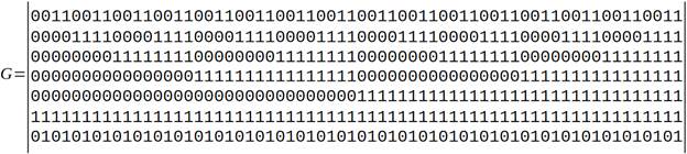
The original value’s most significant bit is multiplied by
the first matrix line, least significant bit – to the last, results are modulo
2 summed.
Resulting value is scrambled by modulo 2 summing (XOR) with
0111000110011101100000111100100101010011010000100010110111111010 as the bit
sequence.
Used coding is fully equivalent to the one used in DVB-S2
(section 5.5.2) and CCSDS 131.2-B-1 (section 5.3.3), despite being defined
differently.
The PLS code carries FEC codeblock
info.
Currently, only one coding is implemented with 2 possible
coded block sizes:
|
PLS
code |
Coding |
Data
block size, with header, in bytes |
|
0 |
½
Viterbi with 255,223 Reed-Solomon |
223 |
|
1 |
½
Viterbi with 255,223 Reed-Solomon* |
48 |
*When using a data block with a size smaller than
Reed-Solomon, the remainder should be 0-filled.
All other values are currently reserved.
Data frame
Next, a data frame with its header is sent, which is coded
by the receiver. (Viterbi, Reed-Solomon and scrambling)
Data coding
Viterbi
Viterbi is used as recommended by CCSDS 131/0-B-3, section
3.3.1. But it should be noted, that both syncword and
PLS code are not Viterbi-coded.
Code parameters:
Type: Viterbi
Code rate: ½
Constraint length: 7 bits
Connection vectors: G1=1111001, G2=1011011
G2 is inverted.
Coder scheme is shown below (conforms to CCSDS 131.0-B-3
Fig.3-1):
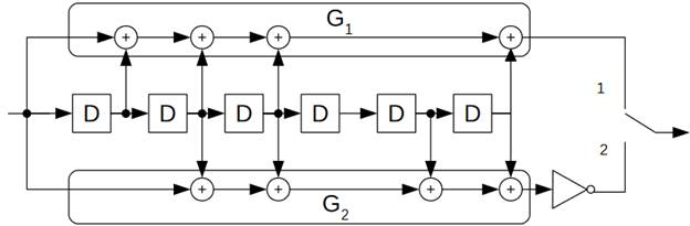
Squares with a D in them signify a 1-bit delay, sums are
all modulo 2. First symbol is set when the switch is in the 1 position.
Scrambling
A scrambler, compliant with CCSDS 131/0-B-3 section 10.4.1
is used.
Scrambling is done by XORing with a polyneme shown below:
h(x) = x8 + x7 + x5 +x3
+1
Reed-Solomon
Reed-Solomon (255,223) code is used as per CCSDS 131/0-B-3,
part 4.
Reed Solomon code trimming
If the data block (frame with header) defined by PLS code
is less than the data block, trimming is performed by zero-padding in front
until Reed-Solomon block is reached, coding, and cropping the additional zeroes
before scrambling and Viterbi encoding. On the receiving side the zeroes are
added back. This procedure is called “virtual filling” and based on the fact
that Reed-Solomon is systematic coding, and appends itself at the end of the
data instead of changing the data. Code cropping conforms to section 4.3.7 of
CCSDS 131/0-B-3 standard.
|
175 bytes |
48 bytes |
32 bytes |
|
Zero pad |
Data block |
Reed-Solomon control symbols |
Gray colored area is the discarded data before scrambling,
and recovered after descrambling.
In case the data frame with the header are shorter than the
data block, the data block also gets zero-padded, but the padding is not
discarded.
Frame structure
Data frame generally is preceded with a 2
byte header, consisting of a type field, which is IEEE 802.3 EtherType.
Length field is generally not provided. If encapsulating
other protocols into USP (with EtherType
highlighting) that use external framing, i.e. without a length field, adding
one might be required. A 2-byte little-endian sequence is recommended for such
a field. The length should include all data encapsulated by the protocol, but
should not include any USP headers. In other words, all data after the byte
length field.
The data block looks like this:
|
EtherType |
Packet data |
|
16 bits |
0-221 bytes |
|
Big endian |
- |
If encapsulating the protocol that requires transmitting
its length, a following structure is recommended:
|
EtherType |
Length |
Packet data |
|
16 bits |
16 bits |
0-219 bytes |
|
Big endian |
Little endian |
- |
Data integrity control
USP does not use a dedicated control sum for integrity
control. It relies on Reed-Solomon, which delivers good enough control.
AX.25 packet transfer using USP
AX.25 encapsulation is done similarly, but not identically
like the AX.25 BPQ protocol made for such a purpose.
In this case, 08FFh in big endian and FF08h in little
endian is used in the EtherType field. It is not
official, but is a de-facto standard in already existing implementations.
Before the AX.25 header, a length value is inserted, that
carries the AX.25 packet length, including its header length. It should be
noted, that the length value is not the same as the AX.25 BPQ implementation
for EtherNet, which adds 4 additional bytes to
eliminate the confusion and problems, arising from length differences.
HDLC framing is also not used. In other words, the flags
and checksum are not sent, and bit stuffing is also not used. The task of determining the packet
length is played by the length from the frame header, and the integrity control
is carried out by means of the USP.
The final data block looks like this:
|
EtherType=08FFh* |
Length |
AX.25 header |
AX.25 Packet data |
|
16 bits |
16 bits |
15-31 bytes** |
0-203 bytes |
|
Big endian |
Little endian |
- |
- |
*FF08h in little-endian
**in a typical spacecraft telemetry case of using
unnumbered frames, the header length is 16 bytes. The max length shown here is
applicable only to this case. For different header lengths, the maximum data size
should be adjusted.
For HEX-dump packet verification, Wireshark in dummy header
mode or with addition of a random 12-byte MAC-address can be used.
Appendix 1. Protocol energy capabilities.
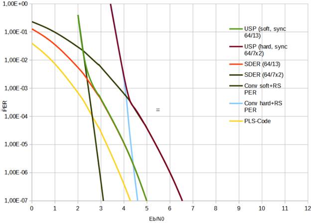
The energy capabilities are shown in the graph below in Eb/N0
form. The graph is shown in 2 variants: with soft decoding (with Viterbi
decoding and 13 bitflips) and with hard decoding (up to 7 bitflips in each syncword half).
The
contribution of individual components is also shown - the probability of a
synchronization error, the probability of incorrect reception of the PLS code
and the error probability when decoding the packet.
From the graph below it can be
seen that, with the AGWN model, when using the soft decoding method at Eb/N0 of
around 2.8, the probability of a good frame decode is 99.9%. (PER <= 0.001)
When decoding with the hard method, the same decode
probability is achieved at Eb/N0 of around 4.1.
Appendix 2. Syncword
The syncword is bit-balanced, has
a maximum of 5 consecutive zeroes and 5 consecutive ones.
The syncword is optimized in such
a way, that it has a good autocorellation by both
itself, and its first half – by itself and with the addition of a 0x55
preamble.
A autocorellation
function graph for the three use cases in the Hamming distance space is shown
below. 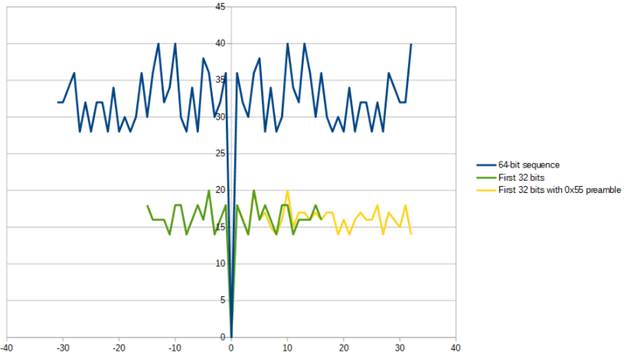
Appendix 3. Explanation of the used technical solutions
A review of already existing protocols
Before creating our own protocol, already existing
protocols were analyzed. The following protocols were analyzed:
·
CCSDS 131/0-B-3 TM synchronization and channel
coding
·
GOMspace NanoCom U482/AX100 UHF transceiver protocol in ASM and ASM+golay modes.
·
AAUSAT-4 protocol
·
AO-40 FEC protocol family and their
modifications
All protocols mentioned above use FEC. Below are short
descriptions and explanations on why the protocols were not used without
modifications.
CCSDS 131/0-B-3 TM synchronization and channel coding
https://public.ccsds.org/Pubs/131x0b2ec1s.pdf
This protocol is the base on which USP is built. The main
problem of using this protocol in half-duplex low speed data links is the lack
of ability to dynamically change frame length, which leads many protocols to
using the channel ineffectively, big round-trips and, as a consequence, slowing
down transmissions.
GOMspace NanoCom
U482/AX100 UHF transceiver protocol in ASM and ASM+golay
modes
This protocol has a length field, which allows it to have
smaller packets when needed. But, it has its downsides as well. The protocol
uses a pretty small syncword, and a uncoded length field, which limits the energy of the
channel to values way too far from FEC abilities.
AO-40 FEC protocol family and their modifications
https://www.amsat.org/articles/g3ruh/125.html
The protocol is well optimized from the point of signal
fades and has good energetic capabilities. The problem is the same as in CCSDS
131/0-B-3 TM: no ability to dynamically change the frame length.
Changelog
v1.01: First publicly available version.
v1.02: Syncword was changed in
order to improve autocorellation of its first half.
This improved reception on hardware receivers drastically.
v1.03: Syncword improved even
more. Now it is optimized by both full autocorellation,
and partial autocorellation – with preamble and
without one.
v1.04: Appendixes re-numbered. Solution explanations elaborated.
Translated by Raov (UB8QBD)