A "stressed" antenna is a good alternative to a solid parabolic reflector. The main advantages are ease of construction, low weight and wind resistance.
It's' known from the theory of resistance of materials that if a deforming force directed along the radius perpendicular to the axis of rotation is applied to the free end of a beam clamped on one side, then the equation of the elastic line of the generator is a parabola. But on practice, not all parabola types can be realised this way. Main criterias are the parabola's F/D (focal distance to diameter) ratio and the length of its generatix. Calculations show that that the parabola deviation error increases with decreasing F/D ratio. The deviation error is also linearly increaing with the generatix length.

Image 1: Relation of paraboloid error from F/D and generatix length.
Going from that, if our dish reflector will have a error in its form we will get a de-focused point and there will be some attenuation. You can estimate the attenuation with the graph below.

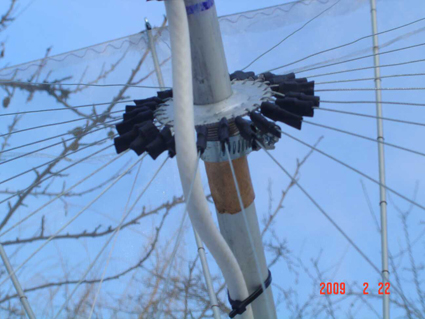
The reflector's "backbone" is made out of 24 aluminum tubes 6mm in diameter and 1m long. The centerpiece was made out of a plastic disc, with a diameter of 200mm and 25mm thickness. The holes for the rods should be 35mm deep.
The tubes have 2mm holes, into which a 1.5mm cable was threaded (6.1m used for this reflector). This should give you a 2m parabola. The cable is threaded with a lanyard,
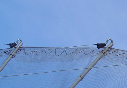
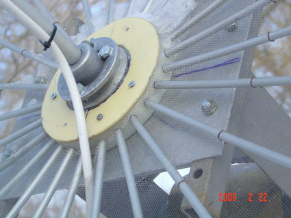
which allows you to fine-tune the tension. Additional axisymmetry of the mirror is supported by 24 wires made of a thin 0.6 mm cable. Their attachment point to the central support tube (12mm in diameter) is shown below:
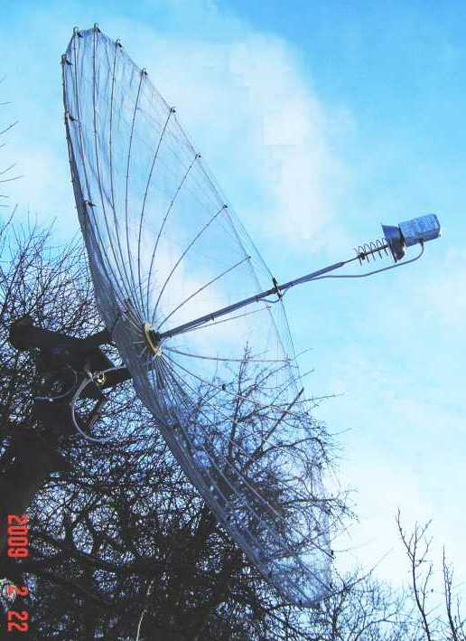
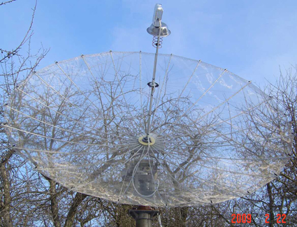
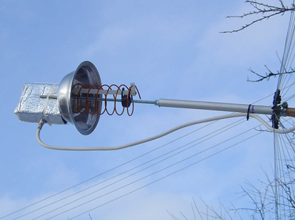
A woven 2x2mm mesh was used, 0.3mm thick. The mesh is attached to the inside of the reflector with a thin copper wire. The ends of the net are wrapped around the main cable and also stitched with a thin wire. Initially for the calculations F/D of 0.5 was assumed, so the main central tube, together with a threaded screw at the end, was in the end a bit longer than 1m. A 1694MHz -> 137MHz downconverter by Radek Vaclavik (OK2XDX) was installed at the focal point with a LHCP helical feed.
Final dish calibration consists of adjusting the axisymmetric supports, main tensioning cable and checking the focal point. After all calibrations we have a 1.95m dish at just 5 kilos! Compared the signal level with METEOSAT-9 (1695MHz) with this dish and a manufactured solid reflector 1.85m dish. When receiving NOAA satellites, the homemade dish showed improvements in signal level, and decoding was successful from 15-20 degrees elevation.
To calculate the lengths of the support generatrix and other parameters, Parabolics and DISH-RUS calculators were used.
Good luck and nice weather! OlegG dx73@ukr.net